PLEASE NOTE: In order to post on the Board you need to have registered. To register please email paul@sexyloops.com including your real name and username. Registration takes less than 24hrs, unless Paul is fishing deep in the jungle!

Upward Force from Form Drag

Moderator: Torsten

Post Reply
User avatar
gordonjudd
Posts: 1859
Joined: Sat Jan 19, 2013 11:36 pm
Answers: 0
Location: Southern California

Upward Force from Form Drag

#1

Post by gordonjudd »

You could do a related experiment by hitting a short section of hanging fly line with the exhaust stream from a vacuum cleaner and see if it rotates to some angle where the downward gravitational force on the fly line reaches an equilibrium angle that depends on the drag-induced lift it has from the air stream
That suggestion was made in one of the detours we took in the transverse wave thread regarding the validity of the analysis in the Gatti-Bono climbing loop paper. Many people said they had never seen such a loop and had reservations about her approach.

My experience in viewing a lot of casting videos is different as it seems to me the loop stays in the air much longer than you would expect if the loop height was dominated by free fall effects as it propagated. For example here is an example where the red dots that tracked the top of the loop in Tom Syversen’s slow motion video of a narrow loop with a long inclined section of line on the bottom of the loop had increasing y values as the loop propagated.
Image

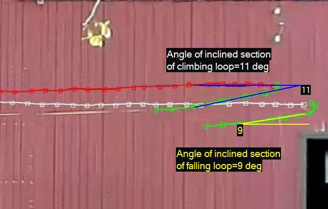
In Tom’s example it appears the track(red squares) for the loop where the inclined section of line was tilted by 11 degrees actually climbed. The loop with a 9 degree inclination did not have enough lift to climb, but still fell at a much slower rate than you would expect if there was not some lifting force to offset the effects of gravity.

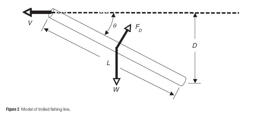
With the help of Dr. Graig Spolek I did some number crunching to see what exposing a tethered length of fly line to different wind velocities might reveal about how much upward force is produced by form drag on an inclined section of fly line. If the air stream is uniform (no so easy to do in practice) then the drag force and the gravitation force along the line will be uniform, and the line will reach a steady state angle where the moment produced by the FD drag force * a moment arm of L/2, will equal the moment produced by the weight of the line * its moment arm of L/2*cos(theta). Dr. Spolek's diagram showing this moment balance situation is shown below:
Image

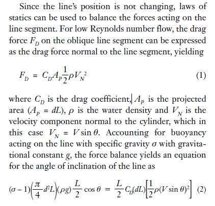
As he summarized in his paper:
Image
This moment balance equation that determines the tilt angle for a given wind velocity was solved for the 8wt line parameters used in this experiment (I used the fzero routine in MATLAB) to produce the curve below.
Image
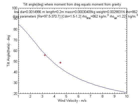
The parameters used for the line are noted in the plot. For the Reynolds numbers expected for this range of wind velocities the Cdn form drag coefficient ranged from 1.5 for a velocity of 1 m/s to 1.2 for the upper velocity of 10 m/s.

Here is short clip of a test showing that the line was surprisingly stable for this air flow of around 3.2 m/s. The dark lines in the video are from the shadows of the fly line and a thin piece of string. I naively thought I could use a thin string to get an idea of how uniform my airstream might be, but since the tension at the end of the string was so small it tended to have a lot of flutter. My .2 m length 0f fly line was much stiffer, so it tended to maintain a reasonably straight shape with little or no flutter.

There was a small amount of angle change for the fly line, but its nominal tilt angle was 56 degrees for the 3.2 m/s wind speed as shown in the measurement below.
Image
The red markers on the tilt angle vs velocity graph show the measured tilt angles for wind velocities of 3.2 m/s and 4.5 m/s. No doubt the airstream I produced with a floor tool attachment on the exhaust of a shop vacuum was not uniform, but you can see the measured values were reasonably close the theoretical curve.

In an actual cast the angle of the inclined section of line would depend on the loop shape not on a moment balance as it was in this experiment. To get an idea of the lift you would expect for the 1 meter length of line having a tilt angle of 11 degrees as measured in Tom’s climbing loop shape here is a plot of how that vertical force (Fd*cos(theta)=the lift component) on the inclined section of a 5wt fly line compares to downward –y directed force of gravity and skin drag (Fs*sin(theta)) over a wider range of loop propagation speeds.
Image
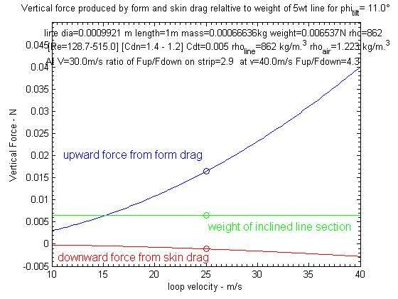
The weight of the total loop would be larger than just the weight of the inclined line section, but as shown in the above graph the lift on the inclined section of line would exceed the weight of that section for loop velocities higher than 15 m/s. For a loop speed of 40 m/s the lift due to form drag would be about 4.3 times higher than the combined downward force from gravity and skin drag on that 1 meter tilted line section.

That Fup/Fdown ratio would be smaller for a heavier line since the form drag varies with the diameter of the line while its weight would vary as its diameter squared. Thus I would doubt you would ever see a climbing loop with a full sinking fly line.

Gravity and drag produce relatively small forces (line weight was .0065N for this example) but if you can produce a narrow Sexyloop shape with high line speeds it would not surprise me to see that they would seem to defy gravity and stay airborne much longer than you would expect for a loop with no upward force from form drag.

Gordy
User avatar
Graeme H
Posts: 2894
Joined: Fri Jan 25, 2013 2:54 pm
Answers: 0
Location: Perth, Western Australia

Upward Force from Form Drag

#2

Post by Graeme H »

Hi Gordy,

Are you saying here that the loop is lifting the fly leg? Or are you saying the fly leg is being lifted by drag as it progresses forward due to its "angle of attack" against the wind?

Cheers,
Graeme
FFi CCI
User avatar
Graeme H
Posts: 2894
Joined: Fri Jan 25, 2013 2:54 pm
Answers: 0
Location: Perth, Western Australia

Upward Force from Form Drag

#3

Post by Graeme H »

In the meantime, here's a video for you to analyse if you like. I made the video as an experiment about the effect of "gravity pullback" on the rod leg. An inclined rod leg has a higher vector of pullback arising from gravity which is not as strong when the rod leg is horizontal (vector diagram required to see this effect.)


For reference, the vertical lines on the building are 6.25m apart and the black marks on the line are 1m apart, starting from the end loop on the line. The leader is also 1m long.

To make these loops "climb", I simply aimed the line upwards. The fly leg continues on that projectile trajectory regardless of how much I pull back or down on the rod leg (Newton's 1st Law). (If you get the time, please put dots on the marks of the rod leg too to show how they drop.)

Cheers,
Graeme

(PS - the wind was blowing from screen right. There are also climbing loops made casting the other direction on the day but the poor light on the line made it too hard to show those casts well.)
FFi CCI
User avatar
gordonjudd
Posts: 1859
Joined: Sat Jan 19, 2013 11:36 pm
Answers: 0
Location: Southern California

Upward Force from Form Drag

#4

Post by gordonjudd »

Or are you saying the fly leg is being lifted by drag as it progresses forward due to its "angle of attack" against the wind?
Graeme,
I am thinking about a loop propagating in the horizontal direction so the fly leg would drop to a tilt angle where its form drag would offset the force of gravity, i.e. the fly leg will be self supporting just like it was in my experiment.

Thus the upward force from form drag on an inclined section of line would impact the drop of the overall mass of of the rest of the loop relative to gravity and help to hold up its end of the catenary shape of the line on the rod leg.

I agree the propagation of the loops in your video seemed to be dominated by their launch angle and don't have much of an inclined section of line on the bottom of the loop.

Maybe the direction of rho_l*v_loop.^2 force on the rod leg dominates the direction the fly leg is being pulled.

Gordy
User avatar
Graeme H
Posts: 2894
Joined: Fri Jan 25, 2013 2:54 pm
Answers: 0
Location: Perth, Western Australia

Upward Force from Form Drag

#5

Post by Graeme H »

gordonjudd wrote: I am thinking about a loop propagating in the horizontal direction so the fly leg would drop to a tilt angle where its form drag would offset the force of gravity, i.e. the fly leg will be self supporting just like it was in my experiment.

Thus the upward force from form drag on an inclined section of line would impact the drop of the overall mass of of the rest of the loop relative to gravity and help to hold up its end of the catenary shape of the line on the rod leg.
Hi Gordy,

Can you find an example video somewhere online that shows the cast? Maybe shoot one yourself if you can't find one? I'd like to have a play and see what it takes to replicate that cast. I think it would be an unusual cast that could be useful in some situations.

Cheers,
Graeme
FFi CCI
Geenomad
Posts: 436
Joined: Tue Aug 06, 2013 10:11 pm
Answers: 0
Location: Melbourne

Upward Force from Form Drag

#6

Post by Geenomad »

G'day Guys
Hope this isn't a distraction but in Graeme's vid I saw something that made me think of drag but not lift.

If you stop it at 1.20secs there is a dark spot on the wall in the centre of the two legs and back a metre or so from the loop. Stop it again at 1.23 and 1.24 the fly leg seems to have risen without the rod leg falling appreciably. It looked to me like the upward deviation from horizontal might be where the faster (following) line goes as drag pushes against the loop front and slows it.

I am open to persuasion on the lift issue but confess it doesn't make intuitive sense to me.

Cheers
Mark
"The line of beauty is the result of perfect economy." R. W. Emerson.
https://thecuriousflycaster.com
User avatar
Graeme H
Posts: 2894
Joined: Fri Jan 25, 2013 2:54 pm
Answers: 0
Location: Perth, Western Australia

Upward Force from Form Drag

#7

Post by Graeme H »

Hi Mark,

Rewind to an earlier part of the same cast (e.g. 1:13) and see where that mark has came from. You should see it's following a roughly parabolic path from down low to the point you've noted at about 1:24. That's just normal projectile motion, being propelled upwards along the path of the line as the cast was being made. (It's a cast with the wind, too.)

How does drag push against the loop front? (Hint: watch any of the marks on the line as they enter the loop. They have no forward motion once they are inside the loop. They go mainly down, not forward, so air resistance only resists downward motion of the mark once it has entered the loop.)

Cheers,
Graeme
FFi CCI
User avatar
VGB
Posts: 6149
Joined: Thu Jan 10, 2013 12:04 pm
Answers: 0

Upward Force from Form Drag

#8

Post by VGB »

I can’t recall anybody claiming that an inclined piece of line with forward velocity would fall at the same rate as a line without forward velocity but it’s still winter, so there’s no harm in strawman arguments. Personally, I’m glad that the claims for climbing loops have been abandoned and that a “falling more slowly” Loop is being seriously considered. I am still somewhat concerned that the conventions of lift and drag relative to freestream airflow are not being correctly observed and that fly casting instead seems to want its own aerodynamic definition.

You may want to look at Spolek paper and consider what Fd1 and Fd2 represent and how this effects your value of Fd represents?

http://flyfishingresearch.net/flydepthr ... iples.html
“Any intelligent fool can make things bigger, more complex, and more violent. It takes a touch of genius — and a lot of courage — to move in the opposite direction.” — Ernst F. Schumacher

https://www.sexyloops.com/index.php/ps/ ... f-coaching
User avatar
VGB
Posts: 6149
Joined: Thu Jan 10, 2013 12:04 pm
Answers: 0

Upward Force from Form Drag

#9

Post by VGB »

the air stream is uniform (no so easy to do in practice) then the drag force and the gravitation force along the line will be uniform, and the line will reach a steady state angle where the moment produced by the FD drag force * a moment arm of L/2, will equal the moment produced by the weight of the line * its moment arm of L/2*cos(theta). Dr. Spolek's diagram showing this moment balance situation is shown below:
In Spoleks analysis, the line is tethered to achieve the steady state, how did you read across that assumption to a loop in flight?

Vince
“Any intelligent fool can make things bigger, more complex, and more violent. It takes a touch of genius — and a lot of courage — to move in the opposite direction.” — Ernst F. Schumacher

https://www.sexyloops.com/index.php/ps/ ... f-coaching
User avatar
VGB
Posts: 6149
Joined: Thu Jan 10, 2013 12:04 pm
Answers: 0

Upward Force from Form Drag

#10

Post by VGB »

gordonjudd wrote: Graeme,
I am thinking about a loop propagating in the horizontal direction so the fly leg would drop to a tilt angle where its form drag would offset the force of gravity, i.e. the fly leg will be self supporting just like it was in my experiment.

Thus the upward force from form drag on an inclined section of line would impact the drop of the overall mass of of the rest of the loop relative to gravity and help to hold up its end of the catenary shape of the line on the rod leg.

I agree the propagation of the loops in your video seemed to be dominated by their launch angle and don't have much of an inclined section of line on the bottom of the loop.
Sorry, I’m getting confused now Gordy. The Gatto Bono paper was about the inclined face of the loop lifting the entire fly line up. It seems your analysis is about the fly leg holding the rest of the loop up. Is that correct?

Vince
“Any intelligent fool can make things bigger, more complex, and more violent. It takes a touch of genius — and a lot of courage — to move in the opposite direction.” — Ernst F. Schumacher

https://www.sexyloops.com/index.php/ps/ ... f-coaching
Post Reply

Return to “Flycasting Physics”