PLEASE NOTE: In order to post on the Board you need to have registered. To register please email paul@sexyloops.com including your real name and username. Registration takes less than 24hrs, unless Paul is fishing deep in the jungle!

The Whip Effect

Moderator: Torsten

User avatar
Merlin
Posts: 2113
Joined: Wed Jan 09, 2013 8:12 pm
Answers: 0
Location: France

Re: The Whip Effect

#51

Post by Merlin »

I used the 2D model to simulate Gordy’s cast with no line. I took known characteristics of the rod (stiffness, speed, mo) and chose a medium action type of rod to characterize non linearity and rod action (bending pattern as a function of load and pull angle). When looking at the video, it is obvious that there are several bending modes involved. In the following picture, one can see two parts of the rod bending in a different direction, and this is the mark of the third mode. So in practice, this rod responded with its three first modes.
No line pic.JPG
No line pic.JPG (31.49 KiB) Viewed 2901 times
The third modes pops up early (200 ms after the beginning for this picture), and although it seems to be there very soon, it can be explained by the speed of the flexural waves in a rod. For such a rod typically (9 foot, #8, 2.7 Hz), the time to travel from one end to the other varies with the mode (figures are rounded):
• first mode: 50 ms
• second mode 30 ms
• third mode 20 ms
When synchronized, the flexural waves and their reflection at ends make the typical modes appear. For this picture, for example, the flexural waves of the third mode already went 5 times up and down along the rod.

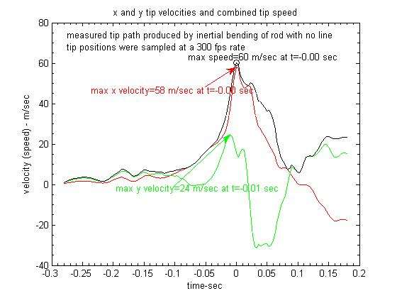
Thanks to Gordy, I had sufficient data to rather closely model the input of the cast, including hand path, and could compare records with the model output. Tip path record shows a wavy aspect due to the higher modes influencing the rod bend, and these waves appear all along the cast. The cast is made of a relatively slow start followed by a drastic impulse which makes the rod bend deeply on the effect of its inertia. This impulse can reach the rotation speed of a competition cast (1000 deg/s approximately).
No line cast simulation.JPG
The main features of the cast are there, but none of the higher modes since the model is by construction unable to find them. Maximum speed of the cast is slightly above 60 m/s,close to Gordy’s measurement, and cancelling the inertial effect drives this speed down by more than 25% which is huge. This impulse influences the beginning of the tip path with a large dip in trajectory (just as the impulse comes in). I stopped the curves at RSP2 for the model. I added some dots on the graphic to give a time scale: each “step” represents 50 ms.

I currently use two damping functions, one before RSP1 and another one after. They are simple functions linked to speed. The model is in advance from the data up to RSP1 (yellow square vs orange circle), which may be relevant of the lack of representation of the current damping model: instead of speed it should involve square of speed (air drag on the rod). After RSP1 this is of less importance, I use nearly the same damping constrain whatever the rod is in that case. I tested a complicate approach with the 1D model, which implies a “spring & damper” device made of caster’s arm (inertia, stiffness, damper), rotating around the elbow. The test was successful with the 1D model (nice rebound), but this is of little practical interest (at least up to know). I shall concentrate on pre RSP1 motion and I have an idea of how to handle the air drag due to the rod. This no line cast is ideal for testing air drag on rod only. Adding air drag effects of the line afterwards does not appear to be too difficult. So I hope being able to answer Bernd’s question about line effect on the cast one of these days.

Merlin
Fly rods are like women, they won't play if they're maltreated
Charles Ritz, A Flyfisher's Life
User avatar
gordonjudd
Posts: 1860
Joined: Sat Jan 19, 2013 11:36 pm
Answers: 0
Location: Southern California

Re: The Whip Effect

#52

Post by gordonjudd »

Maximum speed of the cast is slightly above 60 m/s,close to Gordy’s measurement, and cancelling the inertial effect drives this speed down by more than 25% which is huge.
Merlin,
I am impressed with the match of the tip path predicted by your model with the measured data.

Here is the video of that cast which marks the tip path with white dots. The green dots show the expected tip path for a stiff broomstick. The red lines shows the perpendicular deflection of the tip. With no line the deflection at MCF was a little bigger than the deflection around MAV.
Image

The predicted max tip speed in your model was very close to the measured value of 60 m/s as shown below. Impressive!
Image

Gordy
User avatar
Merlin
Posts: 2113
Joined: Wed Jan 09, 2013 8:12 pm
Answers: 0
Location: France

Re: The Whip Effect

#53

Post by Merlin »

I realize I did come gave information on a model using rod drag. A consequence of covid 19 saga I guess. There were discussions outside the Board up to mid march and here are some illustrations of the outcome.
no line cast simulation with air drag.JPG
no line cast simulation with air drag.JPG (37.49 KiB) Viewed 2364 times
Speed levels
39,9 m/s no drag no inertial effect
36,5 m/s drag no inertial effect
62,1 m/s no drag inertial effect
50,3 m/s drag inertial effect
They are lower than last time, but I use a best guess for the rod, not Gordy’s model one because I do not know the full rod characteristics. Nevertheless the changes are consistent, that is the minimum required.

So for that particular cast the rod drag effect is found to be sensible. I need considering a cast using line to go further. I may then be able to answer Bernd’s question about line density. Among the possible explanations for the different feel induced by line density, there can be skin drag (unlikely IMHO) and inertia due to a different position of the centre of mass of the carry (likely IMHO). A denser line travels lower and reduces inertial torque for the caster.

Drag effect due to the frontal area of the rod during the cast can be estimated with another tricky technique of mine. When considering frontal drag and rotation speed, you end up with estimating drag force applied to rod pieces and a corresponding lever arm. Since the square of speed is involved it is as if the square of lever arm was involved with the square of angular rotation speed. Finally you can consider an element of frontal area multiplied by the square of the chord length corresponding to that element, on top of angular velocity. Then one can define a “MOFA”, moment of frontal area, all along the rod shaft. It is like the MOI but for frontal area instead of mass. Guess what, you have a MOFA for the rod with three components (tip, mid and butt). The values of the various MOFAs change with load, the higher load is, the higher the tip MOFA is and that can be very large in percentage under some conditions. If you consider a straight rod it is something like 1/3, 1/3 and 1/3 of the rod MOFA, roughly.

Then you can compare the various effects of the different parts of the rod, and no surprise if the tip is the main contributor to the torque due to air drag. Here is an illustration for Gordy’s no line cast:
drag torque history no line cast.JPG
drag torque history no line cast.JPG (28.73 KiB) Viewed 2364 times
There is drag torque linked to the butt at the beginning due to caster’s input, but due to larger tip speed, the role of the tip dominates drag by far, as can be expected. This drag contribution does not increase the peak torque (about 22 Nm) but make it last with a higher level of intensity till the end.

Introducing rod drag is possible but not an easy task. Gordy’s no line cast is likely the most sentitive type of cast for rod air drag. I looked at the increase in rod deflection induced by drag and found 8% for this example. Interesting maybe but not applicable to a normal cast I guess.

Merlin
Fly rods are like women, they won't play if they're maltreated
Charles Ritz, A Flyfisher's Life
Post Reply

Return to “Flycasting Physics”