PLEASE NOTE: In order to post on the Board you need to have registered. To register please email paul@sexyloops.com including your real name and username. Registration takes less than 24hrs, unless Paul is fishing deep in the jungle!

Leader Butt Diameter

Moderator: Torsten

Post Reply
User avatar
gordonjudd
Posts: 1860
Joined: Sat Jan 19, 2013 11:36 pm
Answers: 0
Location: Southern California

Leader Butt Diameter

#1

Post by gordonjudd »

If I remember well, the leader diameter at the junction should be 85% of the line diameter. Look after post 39 by Gordon Judd in the thread "leader hinging in slow motion"
Merlin,
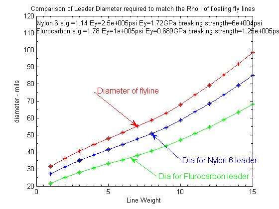
If the aim is to match the leader butt's impedance to the impedance of a floating fly line then the ratio will depend on the type of leader material as well. 85% is a rule of thumb for nylon leaders that have a specific gravity of 1.14. If you use fluorcarbon then its higher specific gravity of 1.78 would reduce that matching impedance diameter to around 2/3 of the line diameter as shown below.
Image
As Jack Moray explained in his leader design approach (that was mentioned by Phillip in the hinging thread) to get the best energy transfer in the leader you want to minimize the difference in the diameter squared ratios from section to section. That generally requires smaller step sizes in the butt and larger step sizes near the tippet end. That approach is opposite of what you see in most leader formulas. The above "ideal" butt diameters are also much larger than the typical diameters used in commercial leaders.

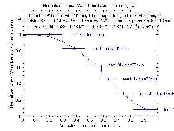
Here is an example of a Moray design where you are trying to get equal step sizes in the linear mass density changes from section to section in a stepped leader.
Image
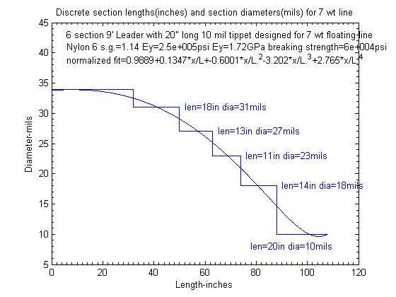
Producing those linear mass density values in a Nylon 6 leader material would use these diameter values where the small changes in diameter are at the butt and the large steps are at the tippet end as shown below.
Image

However as cautioned in the other thread:
Since we are trying to smooth out the layout of the fly getting a maximum transmission of the wave energy through the leader may not be ideal from a fishing standpoint so all of this may be academic.
Gordy
John Waters
Posts: 2199
Joined: Mon Jan 14, 2013 9:16 pm
Answers: 0

Leader Butt Diameter

#2

Post by John Waters »

I remember many lengthy and instructive discussions with Jack Morey, a great fly fisherman and innovative designer. His use of relative specific gravity and leaders tapered by weight, not diameter and modified for stiffness have underpinned my leader designs for both fishing and casting. For example, his 9 feet leader tapered to 4X, for a 5 weight floating line with 6 inches of level line tip, started with 44 inches of 0.024 inch diameter mono. For the same line with an 18 inch level tip on the flyline he used 0.022 inch mono. Some like to remove the level line section from their line, others leave it on. I remove it.

Turnover is important for tournament casting, so why not for fishing.

John
User avatar
gordonjudd
Posts: 1860
Joined: Sat Jan 19, 2013 11:36 pm
Answers: 0
Location: Southern California

Leader Butt Diameter

#3

Post by gordonjudd »

His use of relative specific gravity and leaders tapered by weight, not diameter
John,
His taper depends on the linear mass density of each section, which depends on the volume mass density of the material and the square of the diameter of a given section. (i.e., Rho_l=rho*area) Thus his design relies on both the specific gravity of the material and the diameter squared of each section.

I think he based the shape of the normalized rho_l vs length curve on his experience with different tapers as Phillip and I modified his stated procedure a bit to come up with section lengths that matched the ones he actually used in some of his examples.

Nevertheless his recommendation that the taper diameters be set based on the the square of the diameter of the diameters rather than just the diameter was new to me. From an impedance standpoint that makes perfect sense in order to maximize the energy transmission down the leader if that is your goal.

I wish that I would have had the opportunity to interact with him, as I think he was before his time in regards to applying some physics to the design of leaders.
and modified for stiffness have underpinned my leader designs for both fishing and casting.
Do you know how the bending stiffness of each section was taken into account in order to modify the values given by equal steps in the linear mass density of each section? I would think that would be another important factor, but the above example for a 7wt line did not take bending stiffness into account.

Thanks for your comments.

Gordy
User avatar
Paul Arden
Site Admin
Posts: 19690
Joined: Thu Jan 03, 2013 11:20 am
Answers: 2
Location: Belum Rainforest
Contact:

Leader Butt Diameter

#4

Post by Paul Arden »

Thanks guys I didn't know about stepping up leader diameter with sinking lines. I must have missed that!

Cheers, Paul :)
It's an exploration; bring a flyrod.

Flycasting Definitions
User avatar
gordonjudd
Posts: 1860
Joined: Sat Jan 19, 2013 11:36 pm
Answers: 0
Location: Southern California

Leader Butt Diameter

#5

Post by gordonjudd »

Thanks guys I didn't know about stepping up leader diameter with sinking lines. I must have missed that!
Paul,
You are in good company. I don't think that most people think about the linear mass density matching of line to leader when it comes to sizing a leader butt diameter. The importance of how linear mass density impacts the dynamics of a flyline does not receive the attention it deserves.

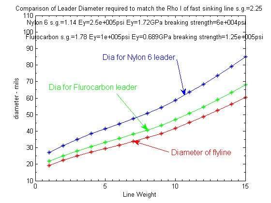
The rho_l and diameter of the sinking line will depend on its sink rate (which is associated with its specific gravity) but here is what the matching curve would like for a fast sink line having a specific gravity of 2.25 assuming it would meet the AFTMA design standards for the mass of 30 feet of line.

Image

I don't know how much trouble you might have in connecting a large diameter mono line to a smaller diameter sinking line, so there may be some problems in actually matching up the rho_l of the leader butt to the tip of the sinking line as discussed in this article at the CastFlys.com site.

Gordy
User avatar
Merlin
Posts: 2113
Joined: Wed Jan 09, 2013 8:12 pm
Answers: 0
Location: France

Leader Butt Diameter

#6

Post by Merlin »

I repeat here the post I made on the other thread, for the consistency of this one.
There are two important parameters for line flight which are the diameter of the line and its « linear density » (in other words the weight by unit of length). The higher they are, the better for the roll over.

Since the loop can be considered as a wave, Gordy explained that the transmission of energy will be maintained if the linear density is conserved as the material change (string wave theory). The linear density is the product of the volumetric density (usually named the density) by the section area of the line. If the density of the material changes for a higher one, then the diameter must decrease. The section area of the line and the leader being proportional to the square of their diameter, the calculation is easy.

Let’s say my line is has a 2 mm diameter. I take 1.2 g/cm3 for the leader and 0.85 g/cm3 for the floating line. Then the diameter of my leader should be equal to the square root of (0.85*2^2)/(1.2) = 1.68 mm. In such condition the linear density of the line is the same as the linear density of the leader. I made the calculation for you; it is equal to 2.67 g/m.

The thing is although I maintain the linear density, I cannot keep the same diameter, so for line flight, I am going to lose something in terms of air drag.

If the situation is reversed, for example if you use a sinking line, then the leader diameter should be larger than the line diameter, because of the respective values of density of the materials.
Ben’s remark appears to be a result from experience matching the theoretical expectations for sinking lines, I wonder if other people have the same experience since it is quite unusual, as noted by Paul.

Gordy

I’m not sure to follow the logic of Jack Moray : where do the guideline curves come from? A best guess? Something theoretical? Since leader density is a constant (if you don't mix materials), then I cant' see impedance conservation here. OK, I'm not going to open an issue on "COI" (conservation of inpedance), it is just to understand the logic behind. :D

Merlin
Fly rods are like women, they won't play if they're maltreated
Charles Ritz, A Flyfisher's Life
Bryan
Posts: 6
Joined: Mon Mar 10, 2014 8:52 am
Answers: 0

Leader Butt Diameter

#7

Post by Bryan »

Enlightening, indeed.

So, then the challenge of how to attach a larger diameter leader to the end of a sinking line? Reading the article and watching the videos at the Castflys.com website, raises a couple of initial quesitons:

1. The twisted leader solution to the larger diameter leader conundrum relies on a loop to loop connection. Won't that itself cause hinging and offset (or worse) the benefit of using a larger diameter leader butt?

2. The No Name Knot used to attach the twisted leader to the tippet seems like a one-shot deal. Once you've tied the tippet to the loop end of the twisted leader using that knot, it seems you can't replicate it on that twisted leader---the loop end has been used. So, what next when you have to replace your tippet? Cut the tippet some distance away from the No Name Knot and attach new tippet? Or, use a new twisted leader?

I appreciate the input folks are putting in here. Improving my leader design and construction is something I'm keenly interested in learning more about.

Thank you.

Cheers,

Bryan
User avatar
Paul Arden
Site Admin
Posts: 19690
Joined: Thu Jan 03, 2013 11:20 am
Answers: 2
Location: Belum Rainforest
Contact:

Leader Butt Diameter

#8

Post by Paul Arden »

I suppose with the higher density lines it makes more sense to use a polyleader. But then you have the cursed loop to loop connection again. Lots to think about!

Thanks, Paul
It's an exploration; bring a flyrod.

Flycasting Definitions
User avatar
gordonjudd
Posts: 1860
Joined: Sat Jan 19, 2013 11:36 pm
Answers: 0
Location: Southern California

Leader Butt Diameter

#9

Post by gordonjudd »

I’m not sure to follow the logic of Jack Moray : where do the guideline curves come from? A best guess? Something theoretical?
Merlin,
I think his normalized curve shape came from experience. As I said in order to get section lengths that matched up with his examples I had to use the "experience-based" normalized curve rather than strictly following the iteration procedure he spelled out in his method. He was doing his calculations with a calculator and graph paper, so cutting corners on calculations might have been a practical necessity. Also he may have found that to get a better lay out of the fly he lengthened the section lengths of the tippet end of the leader to eliminate the splash down effect when fishing dry flies.

Good tournament casters will lengthen (or shorten) the tippet on their dry fly leaders to get the fly to "hover" over the ring at the end of the cast so that they can better judge distance. A 1-2" difference in tippet length will make a big difference in how the fly hovers for them, but I was never that sophisticated. Thanks to John Napoli at the Long Beach Casting Club for showing me that adjustment trick many years ago.

I would expect that based on practical experience Jack Moray used different normalized curve shapes for different situations as well. I have noticed that Rajeff's Bass Bug leader design has a convex slope from beginning to end to get a good turn over of the bug. Harvey used a S-shaped curve with longer flatter transitions at the tippet end. That tends to produce wiggles in the layout of a long leader to help reduce the drag on dry flies. I expect Moray did the same thing, i.e. developed different normalized rho_l vs distance curves for different types of fishing situations. John may have some examples of the different curves he used.
Since leader density is a constant (if you don't mix materials), then I cant' see impedance conservation here.
If you assume the velocity of the wave at the boundaries is the same and knowing that the Tension is proportional to rho_l*v.^2 then the impedance will change whenever you change the linear mass density as shown below.
http://img12.imageshack.us/img12/6982/impedanceequation.jpg

Thus the relative impedance for two adjacent sections will be proportional to their rho_l values which will be proportional to the square of their diameters for a leader made with the same material.

Moray's point was it is better to have a series of nominally equal impedance ratios in each of the transmission loss values rather than having big losses that would result from big impedance ratio differences at the butt end of the leader followed by smaller impedance ratios as you get to the tippet end of the leader.

That approach is in keeping with the guideline given in the Harvard transverse wave paper where the emphasis is on the gradual change in the impedance difference between each section.
The two basic ways to match two impedances are to (1) simply make one of them equal
to the other, or (2) keep them as they are, but insert a large number of things (whatever
type of things the two original ones are) between them with impedances that gradually
change from one to the other.
Since the linear mass density varies as the square of the diameter that means you have smaller diameter steps at the butt end of the leader than you do at the tippet end. That logic makes some sense to me, and is counter to the prescription given in most leader formulas where the big steps are at the butt end followed by smaller steps at the tippet end.
OK, I'm not going to open an issue on "COI" (conservation of inpedance), it is just to understand the logic behind.
You can breathe a sigh of relief. Just as COM does not apply to the predicting the fly velocity history in a normal tethered cast, there is no COI going on with Moray's leader design approach either.

Gordy
User avatar
VGB
Posts: 6224
Joined: Thu Jan 10, 2013 12:04 pm
Answers: 0

Leader Butt Diameter

#10

Post by VGB »

Gordy

in your assumptions, are you assuming that the fly line/leader is a string wave?
“Any intelligent fool can make things bigger, more complex, and more violent. It takes a touch of genius — and a lot of courage — to move in the opposite direction.” — Ernst F. Schumacher

https://www.sexyloops.com/index.php/ps/ ... f-coaching
Post Reply

Return to “Flycasting Physics”