PLEASE NOTE: In order to post on the Board you need to have registered. To register please email paul@sexyloops.com including your real name and username. Registration takes less than 24hrs, unless Paul is fishing deep in the jungle!

Two heads - drag forces compared

Moderator: Torsten

User avatar
Merlin
Posts: 2113
Joined: Wed Jan 09, 2013 8:12 pm
Answers: 0
Location: France

Re: Two heads - drag forces compared

#11

Post by Merlin »

Hi Torsten

In your example the long line exhibits higher drag forces, which does not fit the initial observation about line length effect for a given mass:
Why does casting a 30 ft head that weighs 300 grains ‘feel’ so much heavier than a 60 ft head that weighs 300 grains?
IMHO this is an inertia problem.

Merlin
Fly rods are like women, they won't play if they're maltreated
Charles Ritz, A Flyfisher's Life
User avatar
gordonjudd
Posts: 1860
Joined: Sat Jan 19, 2013 11:36 pm
Answers: 0
Location: Southern California

Re: Two heads - drag forces compared

#12

Post by gordonjudd »

However, you have taken the form drag coefficient that you are using for the line as being in laminar flow,
Vince,
from the Wikipedia article on Reynolds number it says:
At low Reynolds numbers, flows tend to be dominated by laminar (sheet-like) flow, while at high Reynolds numbers flows tend to be turbulent.
Torsten has given a nominal Reynolds number of 32,000 in his form drag calculation and 500 million for the skin drag calculation so I would think that would put them well into the turbulent flow region for both forms of drag.

Gordy
User avatar
VGB
Posts: 6199
Joined: Thu Jan 10, 2013 12:04 pm
Answers: 0

Re: Two heads - drag forces compared

#13

Post by VGB »

Gordy
gordonjudd wrote: Thu Jan 05, 2023 6:03 pm Torsten has given a nominal Reynolds number of 32,000 in his form drag calculation and 500 million for the skin drag calculation so I would think that would put them well into the turbulent flow region for both forms of drag.
I quite agree but you are using a Cd of 1 for your form drag which is for laminar flow, instead of somewhere between 0.1 and 0.3 for a cylinder in turbulent flow as described at Post 8. (viewtopic.php?f=11&t=3858#p68458)

Now for the purposes of this exercise, the model has confirmed that the conclusions reached in the head weight thread, that feel during the acceleration phase of the fly leg is primarily due to the inertia effects described by James. The apparent high value of calculated skin drag is most likely due the assumptions of high values of velocity and that the fly leg is not rigid like a stick, particularly on long carries.

Now that we all agree that the freestream airflow during a cast is usually turbulent, we should also be able to settle on the fact that the value of form drag has been grossly overstated in the loop lift models that have been offered in the past and would account for nobody being able to demonstrate this phenomena at any time.

Vince
“Any intelligent fool can make things bigger, more complex, and more violent. It takes a touch of genius — and a lot of courage — to move in the opposite direction.” — Ernst F. Schumacher

https://www.sexyloops.com/index.php/ps/ ... f-coaching
Torsten
Posts: 465
Joined: Tue Jan 22, 2013 7:34 pm
Answers: 0

Re: Two heads - drag forces compared

#14

Post by Torsten »

Hi, just for explanations,

* I've chosen 40m/s to derive an upper bound for the drag force

* form drag is there to make the estimation a bit more realistic, because the line is usually not totally straight towards the airflow

* velocity is projected according to the tilt angle, e.g. 0° means nil form drag and 90° form drag only

* I've chosen a drag coefficient that is plausible for the given Reynolds Number.

* The drop towards a low drag coefficient happens at a larger Reynolds Number range, 3e5 - 3.5e6 (for smooth cylinders)

also called "Critical Flow Regime" - see [1]

- the boundary layer is turbulent in this case and the drag coefficient sharply drops to a minimum 0.2 - 0.3 (known as "drag crisis")

BUT I've computed a lower Reynolds Number in the e4 range, that means we're in the subcritical flow regime.

Turbulent free flow and/or the roughness of the cylinder move the minimum towards lower Reynolds numbers, but the minimum will be shallower as well. I think we're still outside the range when this happens. I've even found studies that predicted an increase of the drag coefficient with higher free flow turbulence intensity.

In general my estimate was just for the case no wind or only very slight wind (otherwise I'd have to consider wind velocity etc.) It's true that we have always turbulences in the air, but the turbulence intensity will be low, because we have a fast moving fly line through a very slowly moving fluid in this case.

In summary, as long as not someone would convince me that the "drag crisis" actually happens for fly lines I'll stick to the Cd value of 1.

I've spend last year a considerable amount of time for research about this subject, because the next iteration of my fly line model will feature aerodynamic drag.

I can't and I don't want to draw any conclusions about other works here, this would be fully OT and outside the scope of this thread.

Greetings,
Torsten

--

Literature:

[1] LIENHARD, John H., et al. Synopsis of lift, drag, and vortex frequency data for rigid circular cylinders. Pullman, WA: Technical Extension Service, Washington State University, 1966.

Attachment:
* all figures from [1], flow regimes, drag coefficient vs. Reynolds number for a cylinder, effects of disturbances upon drag
flow_regimes_cylinder.png
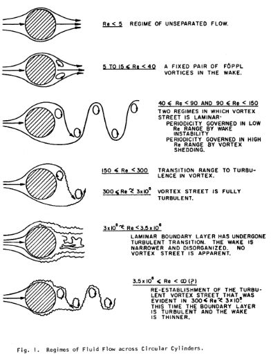
flow_regimes_cylinder.png (134.57 KiB) Viewed 951 times
drag_coefficients_cylinders.png
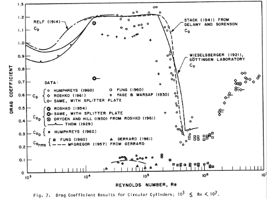
drag_coefficients_cylinders.png (93.42 KiB) Viewed 951 times
effects_of_disturbances_upon_drag.png
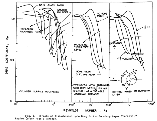
effects_of_disturbances_upon_drag.png (116.25 KiB) Viewed 951 times
User avatar
VGB
Posts: 6199
Joined: Thu Jan 10, 2013 12:04 pm
Answers: 0

Re: Two heads - drag forces compared

#15

Post by VGB »

Hi Torsten

Neither the first figure (laminar flow), nor putting boundary control devices on to your cylinder (3rd figure - right hand side) represent the same turbulent freestream turbulence conditions that you have used for skin drag analysis:
It is clear that there is very little laminar flow. a result anticipated due to the testing in an already turbulent flow which will produce early transition.
I’m not sure what the splitter plate represents in your 2nd figure but the studies are dated. “Mueller TJ, Pohlen LJ, Cnigliaro PE, Jansen Jr BJ (1983) The influence of free-stream dis- turbances on low Reynolds number airfoil experiments, Exp. Fluids 1: 3-14.” Is a better reference.

In the 3rd figure, the rope mesh is producing some freestream turbulence but without any real detail about the degree of induced turbulence. It is well known that the small-scale turbulence along the stagnation line energises the boundary layer around a circular cylinder produces early transition, delays flow separation and reduces form drag. Your rope mesh data seems to acknowledge that effect.

The figure below is wind tunnel data for a cylinder in turbulent freestream flow with values of 2 and 3% turbulence intensity at lower Re numbers than you calculated. It is also worth noting that the study concluded that “the drag coefficient does not change appreciably at high Res

The turbulence intensity was representative of real world data and the data was later used to modify a vehicle:
DA0FD4A5-7A98-41FF-A83C-1F3A048AA24E.jpeg
In summary, as long as not someone would convince me that the "drag crisis" actually happens for fly lines I'll stick to the Cd value of 1……..I can't and I don't want to draw any conclusions about other works here, this would be fully OT and outside the scope of this thread.
That is of course your prerogative but my position is that a Cd of 1 has produced results that have not been verified in the real world, not only in the lift studies but also in the dangle where the line does not straighten even at our highest casting speeds. Given that the line is flexible, a force acting upon it will cause the line to move in order to reduce that force, and there’s little evidence of that occurring in the fly leg, except in strong winds.

I wish you luck in your studies.

Regards

Vince
“Any intelligent fool can make things bigger, more complex, and more violent. It takes a touch of genius — and a lot of courage — to move in the opposite direction.” — Ernst F. Schumacher

https://www.sexyloops.com/index.php/ps/ ... f-coaching
User avatar
VGB
Posts: 6199
Joined: Thu Jan 10, 2013 12:04 pm
Answers: 0

Re: Two heads - drag forces compared

#16

Post by VGB »

Hi Torsten

With regards to the skin drag in subcritical laminar flow, ESDU data provides a drag coefficient of 0.008 for a smooth cylinder and 0.011 for a rough cylinder. At higher Re, they suggest that skin friction may be neglected. However, the study that you quoted indicates the effect that turbulent flow has on drag in general and I think that any model results should be caveated accordingly if you have data that cannot be verified:

https://www.esdu.com/cgi-bin/ps.pl?sess ... gen&p=home

Regards

Vince
“Any intelligent fool can make things bigger, more complex, and more violent. It takes a touch of genius — and a lot of courage — to move in the opposite direction.” — Ernst F. Schumacher

https://www.sexyloops.com/index.php/ps/ ... f-coaching
User avatar
gordonjudd
Posts: 1860
Joined: Sat Jan 19, 2013 11:36 pm
Answers: 0
Location: Southern California

Re: Two heads - drag forces compared

#17

Post by gordonjudd »

In summary, as long as not someone would convince me that the "drag crisis" actually happens for fly lines I'll stick to the Cd value of 1.
Torsten,
Cd=1.0-1.2 is the typical value that I see in nearly all of the papers dealing with the measured form drag coefficient on smooth cylinders in the range of 300<Re<2.e05 as well.
Logarithmic-plot-of-the-drag-coefficient-Cd-as-a-function-of-Reynolds-number-Re-for.png
Logarithmic-plot-of-the-drag-coefficient-Cd-as-a-function-of-Reynolds-number-Re-for.png (37.73 KiB) Viewed 924 times
I have only found one paper https://apps.dtic.mil/sti/pdfs/AD0754889.pdf dealing with the measured drag on inclined thin lines in air but for the Reynolds number range we could expect in casting I think we are safely below the critical flow region that happens for Re values above 3.5e05. That paper:
reference_for_measured_tow_cables.jpg
reference_for_measured_tow_cables.jpg (12.97 KiB) Viewed 924 times
measured a Cd value of 1.0 for an airborne cable with a Reynolds number of 37,000.

What velocity value should be used to calculate the crossflow Reynolds number for an inclined section of line? Should it be the line's x velocity or the effective normal velocity to the line that is equal to Vx*sin(tilt_angle)? For the kind of tilt angles we typically see in distance casts (around 9 degrees) that would reduce the expected Reynolds number by a factor of around 6.4.

Gordy
User avatar
VGB
Posts: 6199
Joined: Thu Jan 10, 2013 12:04 pm
Answers: 0

Re: Two heads - drag forces compared

#18

Post by VGB »

Gordy

It’s worth looking at Torstens last diagram for lower values, I’ve circled the part that indicates turbulent freestream airflow
C36BD8B6-C833-4C26-BF51-B9C02FE84240.jpeg
C36BD8B6-C833-4C26-BF51-B9C02FE84240.jpeg (64.07 KiB) Viewed 919 times
Vince
“Any intelligent fool can make things bigger, more complex, and more violent. It takes a touch of genius — and a lot of courage — to move in the opposite direction.” — Ernst F. Schumacher

https://www.sexyloops.com/index.php/ps/ ... f-coaching
User avatar
gordonjudd
Posts: 1860
Joined: Sat Jan 19, 2013 11:36 pm
Answers: 0
Location: Southern California

Re: Two heads - drag forces compared

#19

Post by gordonjudd »

Neither the first figure (laminar flow), nor putting boundary control devices on to your cylinder (3rd figure - right hand side) represent the same turbulent freestream turbulence conditions that you have used for skin drag analysis:
Vince,
What constitutes turbulent flow?
transition_to_turbulent_flow.jpg
transition_to_turbulent_flow.jpg (27.43 KiB) Viewed 916 times
I look at that first diagram and would think the flow deviates from having smooth flow even at a low Reynolds number of 40.

They say the vortex sheet is fully turbulent for Reynolds numbers above 300, so I would think that the Reynolds number for a fly line would be well above that value.
It’s worth looking at Torstens last diagram for lower values, I’ve circled the part that indicates turbulent freestream airflow
So are you implying that turbulent flow doesn't happen until you reach the crisis flow region for Reynolds numbers above 3.5e-05 even though other researchers say the flow is fully turbulent for Reynolds number values above 300?

Gordy
User avatar
VGB
Posts: 6199
Joined: Thu Jan 10, 2013 12:04 pm
Answers: 0

Re: Two heads - drag forces compared

#20

Post by VGB »

Gordy

Both Gaddis findings and the data I presented are for turbulent freestream flow.
gordonjudd wrote: Wed Jan 04, 2023 5:17 pm At least in the measurements made by Gaddis the opposite was true. He found:
It is clear that there is very little laminar flow. a result anticipated due to the testing in an already turbulent flow which will produce early transition.
Freestream flow is upstream of the object being measured or tested. Looking at the diagram you have presented, it is for upstream laminar flow (circled in red)
503F0B23-C29F-46F2-9551-07B9EC58B2F9.jpeg
503F0B23-C29F-46F2-9551-07B9EC58B2F9.jpeg (30.64 KiB) Viewed 890 times
Real world conditions are rarely laminar due to the effects of wind shear, terrain and atmospherics and turbulence has a significant impact on the aerodynamic performance of any object. I gave you turbulence intensity (TI) data based on 2-3%, this study of a German wind farm site gives real world conditions exceeding 40% but averaging 5-10%:

https://www.sciencedirect.com/science/a ... 0520303664


Vince
“Any intelligent fool can make things bigger, more complex, and more violent. It takes a touch of genius — and a lot of courage — to move in the opposite direction.” — Ernst F. Schumacher

https://www.sexyloops.com/index.php/ps/ ... f-coaching
Post Reply

Return to “Flycasting Physics”